Abstract
Automated industrial production lines rely on consistent, contaminant-free compressed air to sustain reliable performance of cylinders, solenoid valves and pneumatic actuators across continuous shift operations. SMC Type AC FRL Unit integrates three core air preparation functions within one modular assembly to eliminate moisture, stabilize operating pressure and deliver controlled oil mist lubrication for downstream pneumatic hardware. This full-length article breaks down internal structural design, graded performance specifications, diverse industrial deployment scenarios, standardized installation workflows, routine maintenance frameworks, comparative performance benchmarks against alternative air treatment assemblies, and resolved technical troubleshooting queries for pneumatic system design engineers and on-site maintenance technicians. Every section delivers actionable technical guidance to optimize compressed air consistency and extend the service lifespan of all connected pneumatic execution components without relying on fragmented separate filter, regulator and lubricator hardware.
Table of Contents — Click each entry to jump to matching content section
- Core Structural Composition & Integrated Functional Mechanism
- Key Built-In Design Features For Stable Compressed Air Conditioning
- Full Spectrum Industrial Application Fields Across Automated Manufacturing
- Complete Standard Technical Parameter Matrix For AC Series Sizes
- Step-by-Step Standard Installation & Pressure Calibration Workflow
- Comparative Performance Analysis Against Split Air Preparation Components
- Structured Routine Maintenance Schedule & Component Replacement Rules
- Resolved Frequently Asked Technical Questions For Pneumatic Engineers
Core Structural Composition & Integrated Functional Mechanism
Compressed air extracted directly from air compressors carries multiple harmful impurities that degrade pneumatic hardware performance over long-term operation. These contaminants include suspended solid dust particles, condensed water vapor from air compression cycles, residual compressor lubricant oil mist, and micro particulate corrosion fragments generated inside pipeline networks. Unprocessed raw compressed air triggers accelerated seal abrasion, inconsistent actuator movement, internal valve jamming and frequent unexpected line shutdowns in automated assembly, packaging and material handling equipment.
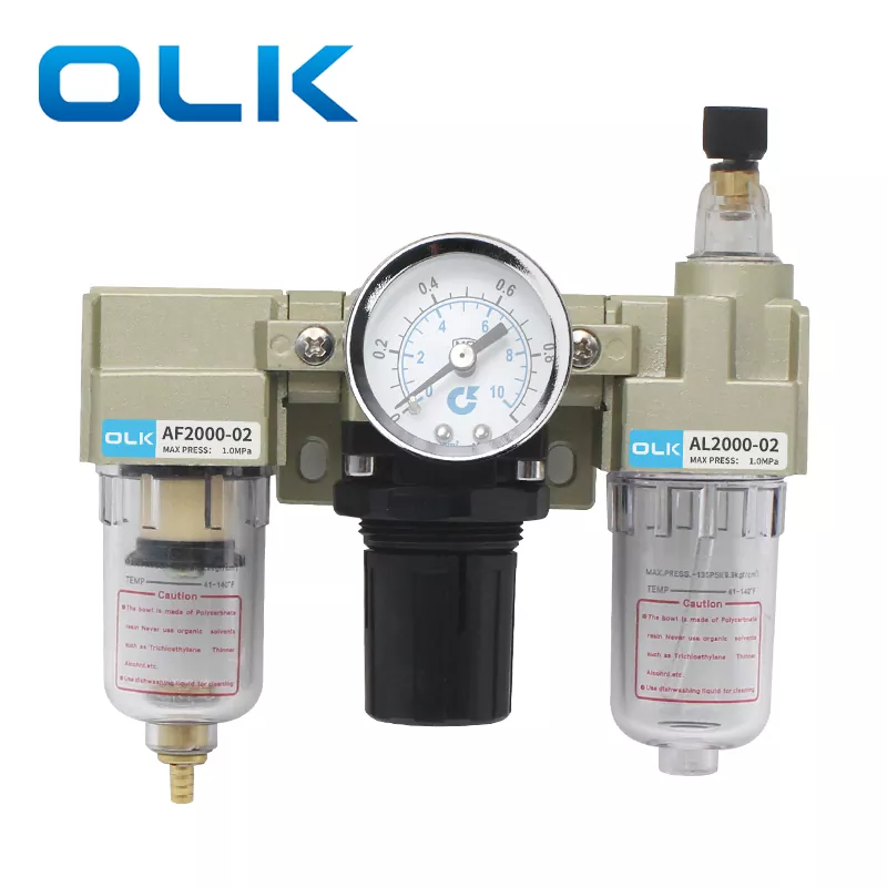
Modular air source processing assemblies resolve these operational risks by combining independent treatment stages into a single compact mounting unit. The unified assembly format eliminates redundant pipe joints, reduces overall system leakage points and streamlines centralized maintenance access for all air conditioning modules. The standard triple combination layout unites three discrete functional blocks into one interlocked aluminum alloy frame, each section performing an irreplaceable conditioning task before air reaches pneumatic actuators and control valves.
AF Air Filter Module
This primary upstream segment intercepts solid particulate matter and condensed water droplets within the incoming compressed air stream. Internally fitted copper filter cartridges achieve 5-micron uniform filtration precision, trapping fine metal shavings, workshop dust and accumulated moisture before these contaminants travel downstream to sensitive regulating and lubricating subassemblies. Transparent polycarbonate storage bowls enable real-time visual monitoring of liquid accumulation without disassembly.
AR Pressure Regulator Module
Positioned centrally within the triple assembly, this module delivers steady output air pressure despite fluctuating input supply pressure from compressors. A spring-diaphragm internal balancing structure automatically offsets pressure surges and drops originating from simultaneous actuator actuation cycles. The adjustable locking knob secures calibrated pressure values to resist drift caused by mechanical vibration during continuous production shifts.
AL Oil Mist Lubricator Module
The downstream lubrication segment atomizes designated pneumatic turbine oil into ultra-fine mist suspended within conditioned compressed air flow. This oil vapor travels through pipelines to coat internal sliding surfaces of cylinders, valve spools and bearing assemblies, lowering metal-to-metal friction coefficients and mitigating dry abrasion damage during millions of reciprocating motion cycles. Adjustable drip rate control allows technicians to match lubrication volume to individual equipment air consumption demands.
- Sequential air flow path strictly follows filter → regulator → lubricator sequence to prevent oil contamination of filter media and pressure balancing internal components
- Interlocking modular connection design removes requirement for custom transition pipe fittings between individual functional segments
- Universal L-shaped metal mounting brackets support vertical panel installation on machine frames, control cabinets and central air manifold stations
- Modular expandability permits supplementary pressure gauges, differential pressure drain attachments and protective bowl covers to be retrofitted post-installation
Every internal flow channel undergoes precision CNC machining to eliminate rough casting surfaces that capture particulate buildup and create localized pressure drop zones. Smooth internal bore geometry maintains consistent air throughput across the full rated flow capacity range, avoiding performance bottlenecks during simultaneous multi-actuator operation peaks. Engineers designing centralized air distribution systems prioritize integrated triple assemblies over separate standalone filter, regulator and lubricator hardware specifically for this balanced flow characteristic and compact footprint advantage within constrained machine enclosure spaces.
Key Built-In Design Features For Stable Compressed Air Conditioning
Industrial pneumatic environments expose air preparation hardware to continuous mechanical vibration, variable ambient temperature cycles, fluctuating inlet air pressure and daily condensate accumulation cycles. Generic low-cost air treatment units lack structural reinforcement and precision adjustment mechanisms required to sustain consistent conditioning performance over multi-year continuous operation. The integrated triple assembly incorporates multiple proprietary design optimizations targeted at eliminating common failure modes observed in conventional split air processing hardware.
Pressure setting stability represents one of the most impactful built-in functional upgrades. The self-locking adjustment knob mechanism removes risk of calibrated pressure shifting after repeated machine vibration cycles. Once technicians rotate the knob to reach target operating pressure, downward axial compression of the knob engages internal tooth locking structures that fix the regulator diaphragm position securely. Accidental bumping or sustained workshop vibration cannot alter preset output pressure values, eliminating frequent recalibration tasks for maintenance staff across daily production shifts.
- Multi-option drainage architecture supporting manual drain, differential pressure automatic drain and full float-type auto drain bowl configurations for matching distinct workshop humidity levels
- High-precision analog pressure gauges with dual-unit metric marking to deliver clear, low-parallax pressure readings during routine line inspection rounds
- Impact-resistant transparent polycarbonate bowls; larger frame sizes 3000 through 5000 include outer protective shielding to prevent bowl cracking during accidental equipment collisions
- Corrosion-resistant die-cast aluminum alloy valve bodies with uniform anti-oxidation surface treatment for extended service life in high-humidity manufacturing facilities
- Graduated oil level marking printed directly onto lubricator bowls to prevent overfilling or insufficient oil supply that compromises actuator lubrication performance
Drainage system versatility addresses variable condensate generation rates across different industrial facilities. Dry indoor workshop environments with low atmospheric moisture content operate efficiently with basic manual drain bowls, requiring scheduled periodic draining during daily equipment shutdown intervals. Facilities with high ambient humidity or water-cooled air compressors benefit from differential pressure drain variants, which automatically discharge accumulated condensate whenever internal pressure differentials reach preset thresholds without manual operator intervention. Fully automatic float drain configurations serve continuous 24-hour unmanned production lines where scheduled maintenance access is limited, draining liquid buildup as soon as condensate levels reach critical heights inside filter storage bowls.
Surface finish and material selection further reinforce long-term operational reliability. All external metal surfaces receive uniform electrostatic anti-corrosion coating to resist oxidation exposure from airborne chemical vapors common within food processing, textile dyeing and metal fabrication plants. Internal sealing gaskets use oil-resistant elastomer compounds compatible with ISO VG32 turbine lubrication oil, resisting swelling, hardening and micro-leakage after thousands of heating and cooling ambient temperature cycles. SMC Type AC FRL Unit combines all these material and mechanical design improvements to deliver steady air conditioning performance unavailable from entry-level non-modular air preparation alternatives.
Full Spectrum Industrial Application Fields Across Automated Manufacturing
Every production workflow utilizing compressed air as primary power transmission medium requires standardized air conditioning to protect precision pneumatic hardware. Without uniform filtration, pressure stabilization and controlled lubrication, automated equipment experiences inconsistent motion output, increased component wear rates and unplanned downtime that disrupts continuous production scheduling. The modular triple assembly adapts seamlessly to diverse industrial verticals with unique compressed air quality and pressure regulation requirements.
Automotive Component Assembly Lines
Robotic clamping fixtures, pneumatic screwdrivers, positioning cylinders and material transfer manipulators demand tightly regulated air pressure to maintain consistent assembly torque and precise part positioning. High-volume automotive workshops generate significant metal particulate contamination from cutting and machining stations; the 5μm copper filter media intercepts fine metal shavings before they damage precision valve spools and cylinder sealing components. Self-locking pressure adjustment eliminates torque fluctuation across thousands of daily assembly cycles.
Food & Beverage Packaging Equipment
Bottle filling machines, carton sealing actuators and labeling stations operate within temperature-controlled environments with elevated ambient moisture levels. Transparent filter bowls simplify condensate monitoring to prevent water droplet contamination of food-grade air supply lines. Lubricator oil mist flow rates can be calibrated to minimal output levels to avoid risk of oil vapor contacting packaged consumable goods, meeting industry hygiene operational standards.
Electronics Precision Assembly Automation
Micro-component pick-and-place robots, circuit board cutting jigs and small-bore positioning cylinders rely on ultra-stable output pressure to eliminate micro-jitter during delicate component manipulation. The low-turbulence internal air flow channels avoid pressure ripple that creates inconsistent actuator movement, reducing component misalignment waste during high-speed surface mount production cycles.
Additional major deployment sectors include textile manufacturing machinery, plastic injection molding auxiliary equipment, pharmaceutical packaging lines, logistics palletizing robotic systems, metal fabrication pneumatic punching machinery and window/door automated processing stations. Each vertical adjusts core unit specifications according to peak air flow demand, operating pressure setpoint, ambient moisture concentration and acceptable particulate contamination thresholds for finished product quality control standards.
Centralized main air manifold installations commonly deploy large frame size 4000 or 5000 assemblies directly downstream from primary air compressor outlets to perform primary bulk air conditioning for entire factory compressed air distribution networks. Smaller frame size 1000 and 2000 variants mount directly onto individual standalone machine control cabinets to deliver secondary localized pressure trimming and filtration for equipment with unique precision operating requirements separate from main factory air supply pressure parameters.
Facility engineering teams standardize on unified modular triple assemblies to simplify spare parts inventory management. Single replacement filter cartridges, regulator diaphragm assemblies and lubricator nozzle inserts fit across matching frame size variants, eliminating the requirement to stock distinct spare component sets for split filter, regulator and lubricator hardware sourced from multiple separate manufacturers. This standardized component compatibility streamlines warehouse spare part organization and reduces lead time delays during urgent on-site maintenance repair operations.
Complete Standard Technical Parameter Matrix For AC Series Sizes
Five distinct frame size classifications cover the full range of industrial compressed air flow and pipeline connection sizing requirements, ranging from compact M5 threaded micro assemblies for small precision robotics up to large 1-inch port variants for factory-wide main air manifold treatment stations. Each frame size carries fixed dimensional limits, maximum throughput capacity, pressure operating windows and interchangeable accessory compatibility rules that engineering teams reference during pneumatic system layout design phases.
| AC Series Frame Model | Standard Port Thread Specification | Max Permitted Working Pressure | Regulating Pressure Range | Filter Bowl Protective Cover Included |
|---|---|---|---|---|
| AC1000 | M5 × 0.8 | 1.0 MPa | 0.05 – 0.7 MPa | No |
| AC2000 | PT 1/4 | 1.0 MPa | 0.05 – 0.85 MPa | No |
| AC3000 | PT 3/8 | 1.0 MPa | 0.05 – 0.85 MPa | Yes |
| AC4000 | PT 1/2 / PT 3/4 | 1.0 MPa | 0.05 – 0.85 MPa | Yes |
| AC5000 | PT 1 | 1.0 MPa | 0.05 – 0.85 MPa | Yes |
Universal fixed mechanical performance benchmarks apply across all frame size variants regardless of port sizing differences, establishing consistent minimum operational standards for the entire series product line:
- Proof pressure testing rating: 1.5 MPa for structural integrity validation during production quality inspection
- Permitted ambient and compressed air fluid operating temperature band: 5°C to 60°C without component performance degradation
- Standard filter media filtration precision rating: uniform 5μm particulate capture efficiency across all AF filter modules
- Designated compatible lubrication fluid grade: ISO VG32 industrial turbine oil for consistent atomization and anti-wear performance
- Bowl base construction material: transparent impact-resistant polycarbonate with printed liquid level indicator markings
Customizable ordering suffix codes enable specification tuning for site-specific operating conditions. Trailing code modifiers define drain mechanism type, integrated pressure gauge mounting orientation and optional supplementary accessories including mounting brackets, flow control attachments and anti-collision bowl protective housings. The standardized ordering structure simplifies cross-regional component procurement and ensures consistent matching replacement unit specifications for identical production line equipment installed across multiple factory locations operated by the same manufacturing enterprise.
Dimensional layout drawings released for each frame size provide precise horizontal and vertical mounting footprint measurements to support control cabinet space planning and machine frame structural design during pre-production engineering phases. Detailed axial and radial dimensional tolerances eliminate installation fit conflicts when retrofitting existing production lines with upgraded air preparation hardware, avoiding costly on-site machining adjustments to accommodate mismatched mounting geometry between legacy split air treatment components and new integrated triple assemblies.
Step-by-Step Standard Installation & Pressure Calibration Workflow
Incorrect assembly, reversed air flow orientation and improperly calibrated pressure settings stand among the top three root causes of premature air preparation unit failure and downstream pneumatic hardware damage. Following a standardized sequential installation checklist eliminates avoidable human error during initial fitting and commissioning procedures, preserving full functional lifespan of the integrated triple assembly and all connected pneumatic execution equipment.
All installation procedures must commence with full depressurization of the factory compressed air supply main line to eliminate risk of sudden high-pressure air discharge during component fitting and connection work. Technicians must confirm compressor system shutoff and residual pipeline pressure venting before handling unit assembly, pipe thread fitting attachment and gauge mounting operations.
- 1. Wrap PTFE sealing tape evenly around external pipe thread fittings before screwing inlet/outlet connectors into unit valve body ports to eliminate air leakage at threaded joints; avoid over-tightening polycarbonate bowl threaded connections to prevent material cracking stress fractures
- 2. Verify directional flow marking arrows printed onto the top surface of the integrated aluminum frame; compressed air must enter the left AF filter port and exit the right AL lubricator port, reversed installation disrupts sequential filtration and contaminates regulator internal components with oil mist residue
- 3. Secure L-shaped metal mounting bracket onto vertical flat machine frame or cabinet panel surfaces with heavy-duty fasteners, ensuring no lateral mechanical play that transmits vibration into the unit body during equipment operation cycles
- 4. Attach calibrated pressure gauge to dedicated gauge port on central regulator module, tightening gauge fittings only with hand torque to avoid damaging internal gauge pressure sensing diaphragms
- 5. Restore low-volume compressed air supply to the unit assembly, lift the central regulator adjustment knob upward to activate pressure tuning functionality; rotate clockwise to increase outlet pressure and counterclockwise to reduce delivery pressure until target setpoint registers on the analog gauge dial
- 6. Once required operating pressure value stabilizes, press the adjustment knob fully downward to engage internal self-locking tooth mechanism and permanently secure calibrated pressure settings against vibration-induced drift
- 7. Unscrew lubricator top oil filling port fastener using standard hex key tool, pour designated ISO VG32 turbine oil into internal reservoir without exceeding printed maximum liquid level indicator line on transparent bowl walls, re-tighten oil port fastener to seal against air leakage
- 8. Fine-tune lubricator oil mist drip rate control screw: clockwise rotation increases oil atomization volume for high air consumption multi-actuator stations, counterclockwise rotation reduces mist output for low-flow precision robotics equipment sensitive to excess oil vapor contamination
Post-installation commissioning validation requires continuous 30-minute full air supply operation under peak equipment load conditions to confirm stable pressure holding performance and consistent oil mist atomization output. Technicians visually inspect all threaded joints, bowl connections and modular interlocking seams for micro air leakage signs via soap bubble testing solution applied to all mating surfaces. Any detectable air seepage requires disassembly, reapplication of PTFE sealing tape and controlled torque re-tightening to resolve joint leakage before full production line operation resumes.
For facility-wide main manifold installations with large frame size AC4000 and AC5000 assemblies, supplementary vibration isolation rubber mounting pads are recommended beneath metal L-bracket mounting surfaces to dampen high-volume compressor vibration transmission into the air preparation unit body. Vibration isolation minimizes long-term fatigue stress on internal regulator diaphragms and filter bowl threaded joints, extending total service interval between complete unit overhauls.
Comparative Performance Analysis Against Split Air Preparation Components
Many pneumatic system design engineers weigh two distinct air conditioning hardware architectures during initial project layout planning: fully integrated triple modular assemblies or three standalone separate filter, regulator and lubricator units linked via intermediate pipe fittings. Each configuration carries unique operational tradeoffs related to installation complexity, space footprint, leakage risk, maintenance accessibility and long-term consistent conditioning performance.
| Performance Evaluation Dimension | Integrated Triple Modular Assembly | Separate Discrete Filter / Regulator / Lubricator Hardware |
|---|---|---|
| Total Pipeline Leakage Risk Points | Minimal internal interlock connections; only two external inlet/outlet threaded joints exposed to leakage potential | Multiple intermediate transition pipe fittings between three discrete units, drastically increasing total air leakage probability |
| Installation Footprint Requirement | Compact unified frame design reduces vertical and horizontal panel space occupancy by 40% on average | Three independent unit bodies demand expanded mounting surface area with separation gaps for individual bowl maintenance access |
| Pressure Drop Through Assembly | Smooth continuous internal flow channels limit incremental pressure loss across full rated flow spectrum | Multiple directional pipe elbow fittings create cumulative flow resistance and elevated system pressure drop during peak air throughput |
| Centralized Maintenance Accessibility | All three serviceable bowls aligned on single vertical plane for simultaneous visual inspection and component replacement | Scattered unit positioning requires separate physical access to three distinct mounting locations for routine inspection tasks |
| Vibration-Induced Pressure Drift Risk | Single rigid aluminum frame eliminates relative component movement between regulator and filter modules | Independent unit mounting allows minor positional shifting under sustained workshop vibration, gradually altering calibrated pressure setpoints |
| Spare Parts Inventory Standardization | Uniform cartridge, diaphragm and nozzle spare components compatible across matching frame size variants from single product series | Discrete hardware from separate product lines requires stocking multiple unique spare component part numbers with limited cross-compatibility |
Separate discrete air conditioning hardware occasionally finds limited deployment within specialized ultra-high-flow industrial pipeline systems where custom spacing between filtration, pressure regulation and lubrication stages becomes mandatory for unique process constraints. For over ninety percent of standard automated assembly, packaging, material handling and precision robotics pneumatic installations, integrated modular triple assemblies deliver superior balanced performance across all measured evaluation criteria listed within the comparison matrix above.
Long-term operational data collected across multi-year production line deployments confirms integrated modular triple units reduce total routine maintenance labor hours by approximately thirty percent annually when compared against equivalent split component setups. Consolidated inspection and component replacement access eliminates repeated technician travel between scattered discrete hardware mounting locations, streamlining daily pre-shift equipment safety and performance validation rounds conducted by facility maintenance teams.
SMC Type AC FRL Unit amplifies these inherent modular assembly advantages through refined internal flow channel machining, reinforced interlocking frame construction and standardized interchangeable spare component architecture unavailable from generic non-series modular air treatment assemblies supplied by competing component manufacturers.
Structured Routine Maintenance Schedule & Component Replacement Rules
Consistent scheduled preventive maintenance directly extends functional service life of air preparation assemblies and prevents unplanned downstream pneumatic hardware failure triggered by degraded filter media, depleted lubricant reservoirs or worn internal regulator sealing components. Establishing fixed inspection and service intervals aligned with equipment operating hours creates predictable maintenance workflows for facility technical staff, eliminating reactive emergency repair scenarios caused by neglected air conditioning hardware degradation.
Daily Pre-Shift Visual Inspection Tasks
Inspect transparent filter bowl for accumulated condensate volume; execute manual drain procedure if liquid reaches half of total bowl capacity. Check lubricator oil reservoir level and replenish ISO VG32 turbine oil before level drops below minimum printed indicator mark. Verify pressure gauge dial reading matches calibrated target operating setpoint, confirming locking knob remains fully depressed to prevent vibration-induced pressure drift.
Monthly Full Functional Service Cycle
Depressurize unit assembly completely, remove filter bowl and extract copper filter cartridge for compressed air back-flushing to clear trapped particulate buildup. Inspect all bowl threaded gaskets for hardening, cracking or minor oil/water seepage signs; replace degraded elastomer seals to eliminate joint leakage risk. Adjust lubricator oil mist drip rate to match updated peak equipment air consumption demands following monthly production throughput reviews.
Quarterly Deep Overhaul Procedures
Fully disassemble regulator module to inspect internal balancing diaphragm for stretching, micro-tears or surface particulate abrasion damage. Clean lubricator atomization nozzle assembly to remove solidified oil residue that restricts consistent mist generation flow. Validate all modular interlock connection seams for air leakage via soap bubble testing solution, retightening loose fasteners and replacing worn interlocking O-ring seals as required.
- Immediate mandatory filter cartridge replacement: filter media displays heavy discoloration from persistent particulate contamination or back-flushing fails to restore consistent air throughput performance
- Regulator diaphragm assembly full replacement: visible pressure fluctuation spikes during stable equipment load cycles indicate internal diaphragm fatigue and material stretching
- Lubricator nozzle component replacement: inconsistent oil mist atomization output persists after thorough solvent cleaning of nozzle internal flow passages
- Complete bowl assembly replacement: polycarbonate housing develops surface micro-cracks or permanent clouding that obstructs clear liquid level visual inspection
All disassembly and component replacement work must strictly follow depressurization safety protocols to avoid sudden high-pressure air discharge during bowl removal and internal module servicing. Maintenance technicians should wear standard eye protection equipment throughout all filter cartridge cleaning, oil refilling and internal regulator disassembly procedures to prevent contact with contaminated condensate or lubrication fluid residue.
Facilities operating within heavily dusty metal fabrication or mineral processing industrial environments should accelerate all scheduled maintenance interval timelines by fifty percent, as elevated airborne particulate concentrations accelerate filter media clogging and internal component abrasive wear rates far above standard workshop contamination baseline levels.
Resolved Frequently Asked Technical Questions For Pneumatic Engineers
1. What does the AC product naming prefix represent in the series triple assembly classification system?
The AC designation combines abbreviations for the three integrated functional subassemblies forming the complete air conditioning triple unit: AF denotes Air Filter, AR represents Air Regulator and AL identifies Air Lubricator. The unified AC label signifies factory pre-assembled interlocked combination of all three core air preparation modules into one single mounting frame, distinguishing this product line from standalone AF, AR or AL discrete component hardware without integrated modular connection frames.
2. What standardized compressed air supply pipeline connection sequence should be implemented for this triple assembly?
The universal industry recommended connection flow path follows compressor main supply line → AC triple assembly inlet port → downstream solenoid valve manifolds, cylinder actuators and pneumatic tool stations. Air must travel sequentially through filter, regulator then lubricator stages in fixed order; reversing inlet and outlet ports introduces irreversible contamination of regulator internal balancing diaphragms by unfiltered particulate and lubrication oil mist residue trapped within filter media chambers.
3. What operational differences separate manual, differential pressure and fully automatic drain bowl configurations?
Manual drain bowls rely on scheduled operator physical actuation to discharge accumulated condensate, suited for low-humidity indoor facilities with predictable daily maintenance shutdown windows. Differential pressure drain variants automatically expel liquid buildup whenever pressure differentials between filter inlet and outlet sides cross preset thresholds, functioning only while continuous air flow passes through the assembly. Full float-type automatic drain systems activate condensate discharge based purely on liquid height inside filter storage bowls, operating reliably during extended unmanned 24-hour production shifts regardless of variable air flow throughput fluctuations.
4. Can non-ISO VG32 alternative lubrication fluids safely be used within the integrated lubricator module?
Unapproved oil viscosity grades or non-industrial lubricant formulations disrupt consistent micro-mist atomization inside the AL lubricator nozzle assembly, leading to uneven coating of internal actuator sliding surfaces or residual thick oil buildup clogging narrow flow passages within downstream valve spool components. Only ISO VG32 turbine-grade pneumatic lubrication oil maintains calibrated atomization performance matched to the internal nozzle dimensional geometry engineered into the series lubricator modules, eliminating risk of premature valve jamming or inconsistent cylinder motion output.
5. How can engineers determine the correct AC series frame size for new pneumatic system layout design projects?
Frame size selection calculations rely on two primary core variables: total peak simultaneous air consumption volume of all downstream connected pneumatic actuators and nominal compressed air pipeline thread port diameter specifications within the facility’s existing distribution network. Matching port thread sizing to pre-installed main supply piping eliminates requirement for custom transition fitting adapters, while selecting frame size with rated flow capacity exceeding peak simultaneous air demand prevents excessive pressure drop and inconsistent actuator motion during full-load production operating cycles.
6. Does the triple assembly support installation in inverted or horizontal mounting orientations?
Zhejiang Ouleikai Pneumatic Co.,Ltd. delivers standardized modular air preparation assemblies engineered to resolve compressed air quality instability challenges across global industrial automation verticals, with full technical documentation and dimensional drawing resources available for all AC series frame size variants.