The SMC Type AC FRL Unit is a modular air preparation assembly combining filter, regulator and lubricator functions for compressed air systems. This article covers core construction, working principles, technical specifications, installation workflow, maintenance guidelines, industrial applications and common operational FAQs. Designed for B2B pneumatic buyers, machine builders and system integrators, the content helps readers evaluate whether SMC Type AC FRL Unit matches their compressed air treatment requirements. Properly selected and maintained FRL hardware protects downstream pneumatic actuators, valves and cylinders from moisture, solid particles and insufficient lubrication, reducing unexpected downtime and component wear across automated production environments.
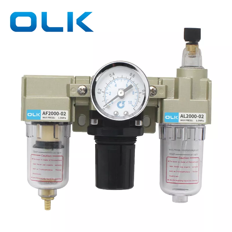
FRL stands for Filter, Regulator and Lubricator. The SMC Type AC FRL Unit integrates these three air processing modules into one compact modular unit. It acts as the front-line air source processor fitted after air compressors and before pneumatic equipment. Raw compressed air generated by air compressors contains water condensate, fine dust particles, pipeline rust and other contaminants. Without air pretreatment, these impurities scratch sealing surfaces, block small valve ports and accelerate aging of rubber seals. Pressure fluctuation from compressor cycling also causes unstable movement of cylinders and pneumatic actuators.
The SMC Type AC FRL Unit solves these common pneumatic system challenges in one assembly. It removes moisture and solid debris, stabilizes output air pressure, and injects controlled oil mist into airflow to lubricate sliding pneumatic parts. The modular AC series design supports easy combination and disassembly, interchangeable body sizes and convenient mounting brackets. This model follows the classic SMC AC series layout and dimensional standard, making it a widely adopted alternative for replacement projects and new pneumatic station builds.
The filter module sits at the inlet side of the SMC Type AC FRL Unit. Incoming compressed air enters the filter bowl chamber. Air flow changes direction, forcing heavier water droplets and large solid particles to settle at the bottom bowl. The fine filter cartridge captures micron-level solid contaminants. The transparent polycarbonate bowl lets operators visually check liquid accumulation without disassembly. Drain options include manual drain and float auto drain versions. Liquid collected inside the bowl must be drained regularly to prevent trapped water from re-entering downstream air pipelines.
After filtration, air flows into the pressure regulator section. The internal spring-diaphragm balancing mechanism compares preset target pressure against real-time outlet pressure. If inlet pressure rises or drops, the regulator automatically adjusts valve opening to keep outlet pressure consistent. The top adjustment knob can be lifted for pressure tuning and pushed down to lock settings. This locking structure prevents pressure drift caused by machine vibration during continuous operation. An embedded pressure gauge offers direct pressure reading for on-site setup and monitoring.
Air moves to the lubricator as the final processing stage. Negative pressure generated by passing air draws pneumatic oil from the storage bowl. Oil turns into fine mist and mixes uniformly with compressed air. The oil mist travels through air tubing and coats contact surfaces inside cylinders and directional control valves. The drip adjustment screw controls oil supply volume. Technicians tune oil drip rate according to total air consumption of downstream pneumatic equipment. Too much oil contaminates process equipment; insufficient lubrication leads to dry friction and shortened service life of actuators.
Air must flow following fixed sequence: filter → regulator → lubricator. Reversed assembly will cause oil contamination of filter cartridge and regulator internal parts, which quickly degrades performance.
| Item | Specification |
|---|---|
| Proof pressure | 1.5 MPa |
| Pressure regulating range AC1000 | 0.05-0.7 MPa |
| Pressure regulating range AC2000~AC5000 | 0.05-0.85 MPa |
| Bowl material | Polycarbonate |
| Filter precision | 5 micron |
| Thread option | G / Rc / NPT |
| Body size | AC1000, AC2000, AC3000, AC4000, AC5000 |
| Series | AW | AC | BR | BFC |
|---|---|---|---|---|
| 2000 series | 1/8 | 1/8 | 1/4 | 1/4 |
| 3000 series | 1/4 | 1/4 | - | - |
The modular construction brings clear advantages for equipment maintenance. When filter cartridge is clogged or bowl components are damaged, maintenance staff only replace the failed single module instead of swapping the complete FRL combination. This reduces spare part inventory cost and shortens equipment downtime during repair cycles.
Correct installation directly affects service life and performance of SMC Type AC FRL Unit. Operators must read all steps before mounting on pneumatic pipelines.
Never install SMC Type AC FRL Unit upside down or reverse airflow direction. Check all thread connections for air leakage after pressurizing the system. Do not apply strong impact to polycarbonate bowl. Avoid environments with strong chemical splashes which may damage bowl material.
SMC Type AC FRL Unit is widely deployed across industries that rely on pneumatic automation. Any compressed air system driving cylinders, air grippers, pneumatic slides or air valves requires air preparation at the front end.
Machine integrators often select SMC Type AC FRL Unit for standardized pneumatic stations. Consistent dimensions and interface standards simplify repeated machine design work. Maintenance teams also benefit from familiar component layout for routine inspection across multiple production machines.
Routine maintenance prevents sudden failures of SMC Type AC FRL Unit and protects downstream pneumatic devices. Create fixed inspection schedules based on operating hours and ambient dust level.
Visual check the transparent bowl. Drain accumulated water from filter bowl every day under high humidity working conditions. Check oil level inside lubricator bowl and refill pneumatic oil when level drops below minimum line. Listen and observe pipeline joints for air leakage.
Verify outlet pressure reading stays stable during machine operation. Check oil mist drip speed and recalibrate if oil feed rate becomes abnormal. Inspect bowl surface for scratches, cracks or chemical erosion marks. Replace bowl immediately if any crack appears to avoid burst risk under air pressure.
Replace filter cartridge regularly. Heavy dust environments need shorter replacement intervals. Replace rubber sealing components when air leakage occurs at regulator or lubricator joints. Always depressurize the whole pneumatic system before disassembly for maintenance work.
Want to know more details about SMC Type AC FRL Unit for your pneumatic project? Browse our product page to check full specifications and dimension drawings.
SMC Type AC FRL Unit Product Page
If you have technical questions about model selection, mounting or customization, feel free to Contact Us. Learn more about our factory at About Us.